
IEC 61215 PV Module Qualification — Which Equipment Carries Which Stress.
A photovoltaic module is qualified against a service life no laboratory can wait out. IEC 61215, the design qualification and type approval standard for terrestrial PV modules, covers crystalline-silicon and thin-film designs alike, and a module that completes its test sequence is taken to have a reasonable expectation of operating reliably for twenty years or more in general open-air climates. Nobody can leave a candidate design outdoors for two decades before selling it, so the standard compresses the damaging part of that exposure into chamber sequences: the accumulated UV dose, the humid summers, the freezing mornings, the wind and snow working on the frame.
The map below follows the qualification sequence the way a laboratory sees it: which stress each test family applies, and which class of equipment carries it. Treat it as a map, not a manual; for procedures, severities and pass criteria there is no substitute for the standard's own text.
The shape of the MQT sequence
IEC 61215 organises its work as Module Qualification Tests, each carrying an MQT number, and the names alone show that the sequence mixes two kinds of activity. Some MQTs measure: visual inspection (MQT 01), maximum power determination (MQT 02), the insulation test (MQT 03), temperature coefficients (MQT 04), performance at STC and NMOT (MQT 06). Others stress: hot-spot endurance (MQT 09), UV preconditioning (MQT 10), thermal cycling over 200 cycles (MQT 11), humidity-freeze over 10 cycles (MQT 12), 1000 hours of damp heat (MQT 13), static mechanical load (MQT 16) and hail (MQT 17). Stabilisation (MQT 19) rounds out the list. A qualification programme is the interplay of the two; the stress legs are read through the measurements.
Two companion documents matter when scoping a programme. IEC 61730, the PV module safety standard, is typically paired with IEC 61215. And the environmental conditioning underneath the climatic legs rests on the IEC 60068-2 series, the same building-block methods that defence and avionics standards reference; for PV work the relevant parts are the cyclic salt mist of IEC 60068-2-52 and the steady-state damp heat of IEC 60068-2-78.
UV preconditioning, and why it runs early
MQT 10 exposes the module to a defined dose of ultraviolet radiation, with the deliberate aim of bringing out materials and adhesion degradation before the thermal-cycling and humidity-freeze tests run. The damage signature is familiar to anyone who has left plastic parts in the sun: yellowing or fading of the coating material, cracking or deformation of plastics, coatings and seals, and a measurable drop in electrical efficiency.
The equipment class is a solar panel UV test chamber, and its job is exact rather than glamorous: deliver the controlled irradiance and the accumulated dose the standard calls for. Dose control is what separates a qualification exposure from leaving a lamp on; the test is defined by the ultraviolet energy the module has received, not by how long the source burned.
The climatic block
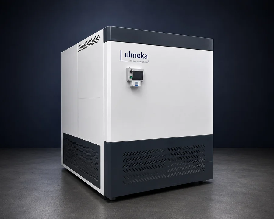
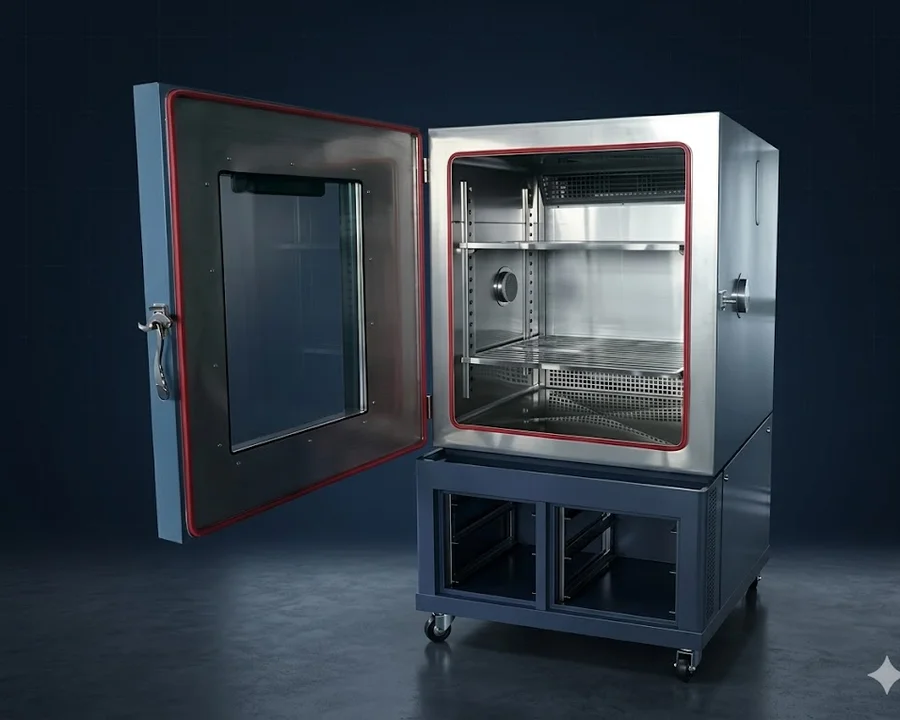
Three MQTs form the climatic core of the sequence, and in the laboratory they usually share one machine: a climatic conditioning chamber running the temperature and humidity profiles defined in IEC 61215-2, the part of the standard that holds the test procedures.
Thermal cycling (MQT 11)
The module rides a series of temperature cycles between -40 °C and +85 °C, two hundred of them, with the temperature held at each limit for a set period. The inspection afterwards looks for what repeated expansion and contraction leave behind: micro-cracks in the cells, connection failures, mechanical deformation in the module build.
Damp heat (MQT 13)
The endurance leg: 1000 hours at 85 °C and 85 % relative humidity, held steady. It gauges whether moisture finds its way into the module's internal structure and what that does to electrical performance, with corrosion and lamination failures the classic findings. Engineers shorthand it as 85/85, and at a thousand hours it occupies the chamber for some six weeks without interruption, which makes it the booking around which the rest of the laboratory calendar tends to be planned.
Humidity-freeze (MQT 12)
Ten cycles in which the module is held under high humidity for a defined period and then frozen rapidly. The pairing is the point. Warm humidity lets moisture in; the sudden freeze turns that moisture into temperature stress wherever it has reached. That is not what damp heat measures, and the standard wants both answered.
One chamber class can carry all three legs. The climatic conditioning chamber in the ULMEKA catalogue, to take a concrete example, is specified to cover the IEC 61215-2 climatic sequences together with the IEC 60068-2-52 salt mist cycle, with the profiles run under PLC and HMI control.
Mechanical load, static and cyclic
Inside the sequence proper, MQT 16 applies a static mechanical load. Outdoor mechanical life is rarely static, though; wind gusts and snow loads come and go, and they come back. IEC TS 62782 addresses the repetitive side with a cyclic dynamic mechanical load test: the module is subjected to repeated push-pull loads to bring out cell cracks and interconnection fatigue, typically as a preconditioning step ahead of further qualification work such as IEC 61215.
This leg needs its own hardware, a load frame that pushes and pulls a mounted module through the cycling the standard defines. What inspectors go looking for afterwards are the micro-cracks and structural deformations that build up under repetitive loading, and the electrical deterioration that follows from them.
Salt mist for coastal duty
Modules installed near a coastline live in an atmosphere loaded with salt, and the long-term threat is corrosion of the panel surface and connection points, along with breakdown of the surface coatings. IEC 60068-2-52 defines the cyclic salt mist test used to assess this, and it is one of the two IEC 60068-2 methods cross-referenced for PV work. In the chamber, a saline solution is sprayed continuously, with the concentration and the spraying duration set by the standard; the spray phase is followed by storage in a humid environment so corrosion effects can develop and be evaluated.
Corrosion findings alone do not close the test. After the saline exposure the module's electrical characteristics are measured, in particular maximum power output (Pmax), open-circuit voltage (Voc) and short-circuit current (Isc), because the question is ultimately whether the module still performs, not merely how it looks. The chamber doing this work has to handle both phases the cycle defines, salt-mist deposition first and humid storage after.
MIL-STD-810 Method 505 is a different question
Laboratories sometimes ask whether a MIL-STD-810 solar radiation chamber and a 61215 UV chamber are interchangeable, since both aim intense light at a specimen. The intents differ. Method 505.7 of MIL-STD-810H states two objectives: to evaluate the heating effects of solar radiation on materiel, and to determine the photochemical degradation, the actinic effects, caused by prolonged exposure to sunlight. It offers two procedures: Procedure I, a cycling test for the heating effects of a 24-hour solar cycle, and Procedure II, a steady-state exposure intensified to accelerate actinic degradation. The chamber produces full-spectrum radiation from xenon arc or metal halide lamps at an intensity of 1120 W/m² ± 47 W/m², with airflow and chamber temperature kept under control so the heating the specimen sees stays representative.
That is materiel durability: will paint surfaces crack and chalk, will elastomers harden, will a mechanism seize because metal parts with different expansion coefficients heated unevenly in the sun. The IEC 61215 UV leg is something else: a preconditioning dose inside a qualification chain, sized to expose adhesion and material weaknesses that the climatic legs which follow are designed to find. Method 505.7 also draws its own boundaries: it is not intended for items housed inside an enclosure, which belong with the high-temperature method 501.7, and not for space applications, where the solar radiation environment differs. The catalogue machine for this method spans a spectral range of 295 to 800 nm with chamber temperature control from 25 °C to 90 °C; the equipment classes are related, but the test plans they serve are not the same, and neither substitutes for the other.
Planning notes for the laboratory
Some of what makes or breaks a PV qualification programme in practice:
- Keep the sequence order in mind. UV preconditioning sits ahead of thermal cycling and humidity-freeze for a reason; its dose sets up the degradation those legs are meant to reveal. Scheduling it elsewhere changes what the chain can find.
- Plan around the damp heat leg. Six chamber-weeks with no break, so book that slot before anything else and make sure nothing on the utility side can cut it short partway through.
- Decide early whether cyclic dynamic load is in scope. IEC TS 62782 typically runs as preconditioning before further qualification, so it belongs at the front of the plan and needs its own load frame, not the climatic chamber.
- Treat salt mist as a deployment question. The IEC 60068-2-52 cycle earns its place when the modules are headed for coastal or similar salt-laden installations; the post-exposure electrical measurements (Pmax, Voc, Isc) belong in the plan from the start.
- Write the measurement points into the plan. The sequence contains measurement MQTs alongside the stress legs; a test plan should state which measurements are taken, and when. Without them a stress result has no baseline to be judged against.
Where ULMEKA fits
ULMEKA designs and manufactures laboratory equipment in the classes described above: solar panel UV test systems referencing IEC 61215, climatic conditioning chambers for the IEC 61215-2 thermal cycling, damp heat and humidity-freeze profiles, cyclic dynamic mechanical load testers to IEC TS 62782, salt mist conditioning chambers to IEC 60068-2-52, and solar radiation test machines for MIL-STD-810H Method 505.7. These are catalogue equipment classes, described here so a test plan can be matched to hardware; the configuration for a particular programme, from chamber dimensions to the exact profiles and instrumentation, is settled at the quotation stage against the standard editions and severities the programme actually invokes.
Sistemas de ensayo relacionados.
Sistemas de ensayo →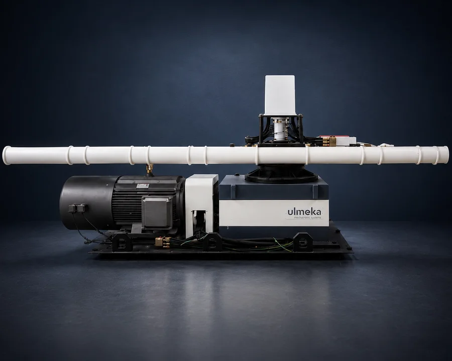
Preguntas frecuentes.
What tests make up the IEC 61215 qualification sequence?
Roughly half the MQTs measure and the other half punish. The measuring side covers visual inspection, maximum power, insulation, temperature coefficients and performance at STC and NMOT. The punishing side runs a UV dose, 200 thermal cycles, ten humidity-freeze cycles, a thousand hours at 85/85, hot-spot endurance, static load and hail, plus stabilisation. A module passes or fails on what the measurement legs show after that treatment.
What are the conditions for the IEC 61215 damp heat test?
A thousand hours at a steady 85 °C and 85 % relative humidity, which is why engineers just call it 85/85. The question it settles is whether moisture works its way into the module's internal structure, with corrosion and lamination failures the usual evidence and electrical performance the casualty. Six weeks of nonstop chamber time is also why the rest of the laboratory calendar tends to be arranged around this leg.
Why does UV preconditioning come before thermal cycling in IEC 61215?
Because the UV dose is the set-up move. MQT 10 brings out material and adhesion weaknesses first, so the thermal cycles and the freeze leg that follow have something to work on; run the dose later and the chain loses that sensitivity. On the module itself the exposure shows up as yellowed or faded coatings, cracked or deformed plastics and seals, and lower electrical efficiency.
What does IEC TS 62782 add to PV module mechanical testing?
IEC 61215's own mechanical leg, MQT 16, is static. IEC TS 62782 covers the loads that repeat: the module is cycled through push and pull to bring cell cracks and interconnection fatigue to the surface, standing in for wind and snow working over years. It typically runs as preconditioning ahead of further qualification, and it needs its own load frame rather than chamber time.
When do PV modules need salt mist testing?
Whenever the deployment site puts salt in the air, with coastal installations the textbook case. The IEC 60068-2-52 cycle sprays a saline solution at a standard-set concentration and duration, then moves the module into humid storage to let corrosion develop. What gets judged afterwards is twofold: the visible state of surfaces, coatings and connection points, and the numbers, since Pmax, Voc and Isc are measured once the exposure ends.
Is a MIL-STD-810 solar radiation chamber interchangeable with an IEC 61215 UV tester?
No, and the difference is intent rather than hardware. Method 505.7 asks what sunshine does to materiel: heating, plus the actinic damage of long exposure, tested under full-spectrum lamps at 1120 W/m² in a cycling or a steady-state procedure. The 61215 UV leg has a narrower job, delivering a set dose so that the climatic tests downstream can find what it weakened. One cannot stand in for the other.
ULMEKA diseña sistemas de ensayo
según especificación.
Si su requisito queda fuera de este catálogo —tamaños de cámara personalizados, integración de normas combinadas o perfiles de ensayo a medida— hable con nuestro equipo de ingeniería.