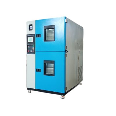
MIL-STD-810H (Method 516.8) Shock (MIL-STD-810G Method 516.6) Test Machine
The MIL-STD-810H (Method 511.7) Shock Test Machine is designed to assess the device’s resistance to impact. During the test, devices are either dropped from a certain height or subjected to an impact to simulate shock effects.
1. Scope
1.1 Purpose:
This test is used to evaluate the resistance of materials to mechanical shocks encountered during transportation, use, and service environments. The objectives of the test are as follows:
- To verify the physical and functional resistance of the material to shocks.
- To determine the material’s fragility level and develop appropriate packaging or assembly methods.
- To test the safety of material fasteners in case of impact and prevent component ejection.
1.2 Application:
This method is used to simulate mechanical shocks that the material may be exposed to throughout its lifespan. In general, such mechanical shocks occur at frequencies not exceeding 10,000 Hz and have durations shorter than one second.
1.3 Limitations:
This test method does not cover the following conditions:
- Shocks caused by the activation of pyrotechnic devices (See Method 517.3 – Pyroshock).
- High-energy shocks resulting from ballistic impacts (Method 522.2 – Ballistic Shock).
- High-impact shocks related to naval combat service (MIL-DTL-901 tests should be applied).
- Pressure wave effects in missile and weapon systems (Method 519.8 – Gunfire Shock).
2. Tailoring Guidance
2.1 Selection of Test Method
The necessity of shock testing should be determined by examining the potential mechanical shock environments the material may encounter during its lifecycle.
2.1.1 Effects of Shock Environments
- Wear and deformation on the material.
- Friction and interlocking between components.
- Circuit failures, magnetic, and electrostatic field disturbances in electronic components.
- Structural collapse and low-cycle fatigue.
2.1.2 Combination with Other Tests
Shock tests can be combined with the following tests to obtain more comprehensive results:
- Method 514.8 (Vibration Test): Simulates the effects of combined shock and vibration.
- Method 525.2 (Time Waveform Replication – TWR Test): Replicates real-world vibration and shock conditions.
3. Test Procedures
Method 516.8 includes eight different procedures depending on the material’s application:
- Procedure I – Functional Shock: Tests the material’s resistance to shocks during operation.
- Procedure II – Transportation Shock: Simulates shocks that the material may experience during transport.
- Procedure III – Fragility Shock: Determines the fragility level of the material.
- Procedure IV – Transit Drop Test: Evaluates the material’s resistance to drops and impacts during logistics processes.
- Procedure V – Crash Hazard Shock Test: Tests the safety of fasteners during a crash.
- Procedure VI – Bench Handling Shock Test: Simulates impacts that may occur during repair and maintenance.
- Procedure VII – Pendulum Impact Test: Tests the durability of large containers and crates.
- Procedure VIII – Catapult Launch/Arrested Landing Test: Measures equipment durability during takeoff and landing in fixed-wing aircraft.
4. Test Process
4.1 Test Facility and Equipment
- Test Systems: Electro-hydraulic vibration tables, drop test systems, pendulum impact systems.
- Measurement Equipment: Accelerometers, strain gauges, laser Doppler vibration meters should be used.
4.2 Test Controls
- Shock Waveform: The applied impact must be in the form of a half-sine, sawtooth, or trapezoidal wave.
- Test Direction: Each material must undergo at least one shock test in the X, Y, and Z axes.
- Temperature Conditions: Shock tests can be combined with high/low temperature tests.
4.3 Test Interruptions
- Laboratory Failure: If the test stops, it should resume from where it left off.
- Material Failure: If the material fails during testing, the cause must be documented, and the test should be repeated.
5. Analysis of Results
Test results should be evaluated based on the following criteria:
- Physical Damage: Cracks, fractures, deformations.
- Functional Failure: Electrical or mechanical component malfunctions.
- Chemical Effects: Changes in material composition.
- Optical Systems: Distortions in lenses and screens.
6. References/Related Documents
- MIL-STD-810H
- MIL-DTL-901 (Naval Shock Test)
- MIL-STD-331 (Fuze and Explosive Component Testing)
- NATO STANAG 4370
- Method 519.8 (Gunfire Shock Test)
Key Features
| Feature | Value / Description |
|---|---|
| Shock Intensity | Between 40 g and 75 g |
| Shock Duration | From 11 ms to 15 ms |
| Height | Free fall from 30 cm to 100 cm |
| Test Method | Application of shock or impact to the device |
| Test Result | The device’s resistance to shocks is evaluated |
Application Areas
- Automotive Devices: Equipment exposed to shock impacts in vehicles.
- Military Devices: Durability after drops or vibrations.
For more information about MIL-STD-810H (Method 516.8) and to place an order, please contact us!